
This is a support page for day 4 of an 8-session class is a basic introduction to both electronics and programming the Arduino microprocessor. The intent is to prepare the student for what is currently popular in the maker world, rather than an electronics or engineering degree, and includes some things of interest to amateur radio enthusiasts.
Day 1, Day 2, Day 3, Day 4, Day 5, Day 6, Day 7, Day 8
Day 4: AC, capacitor, diode, oscilloscope, signal generator, capacitors in series and parallel
Goals:
-
- Draw the circuit symbol for an Arduino, capacitor and diode
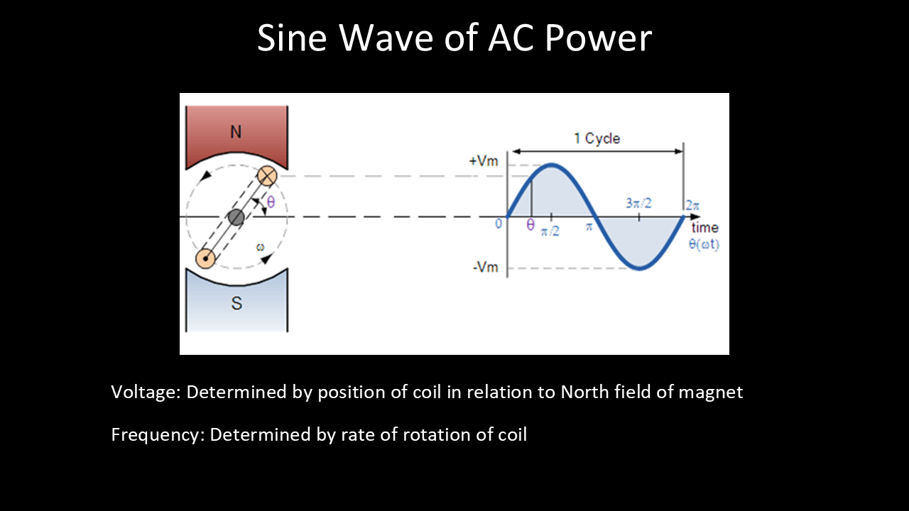
- Understand what alternating current is
- Explain why a pull-down resistor is important
- Explain what an these do:
- Oscilloscope
- Signal Generator
- Capacitor
- Diode
- Understand how capacitors behave in series & parallel
- Explain why a pull-down resistor is important
- Build & code a pushbutton toggle circuit
Vocabulary:
-
- Capacitor
- AC
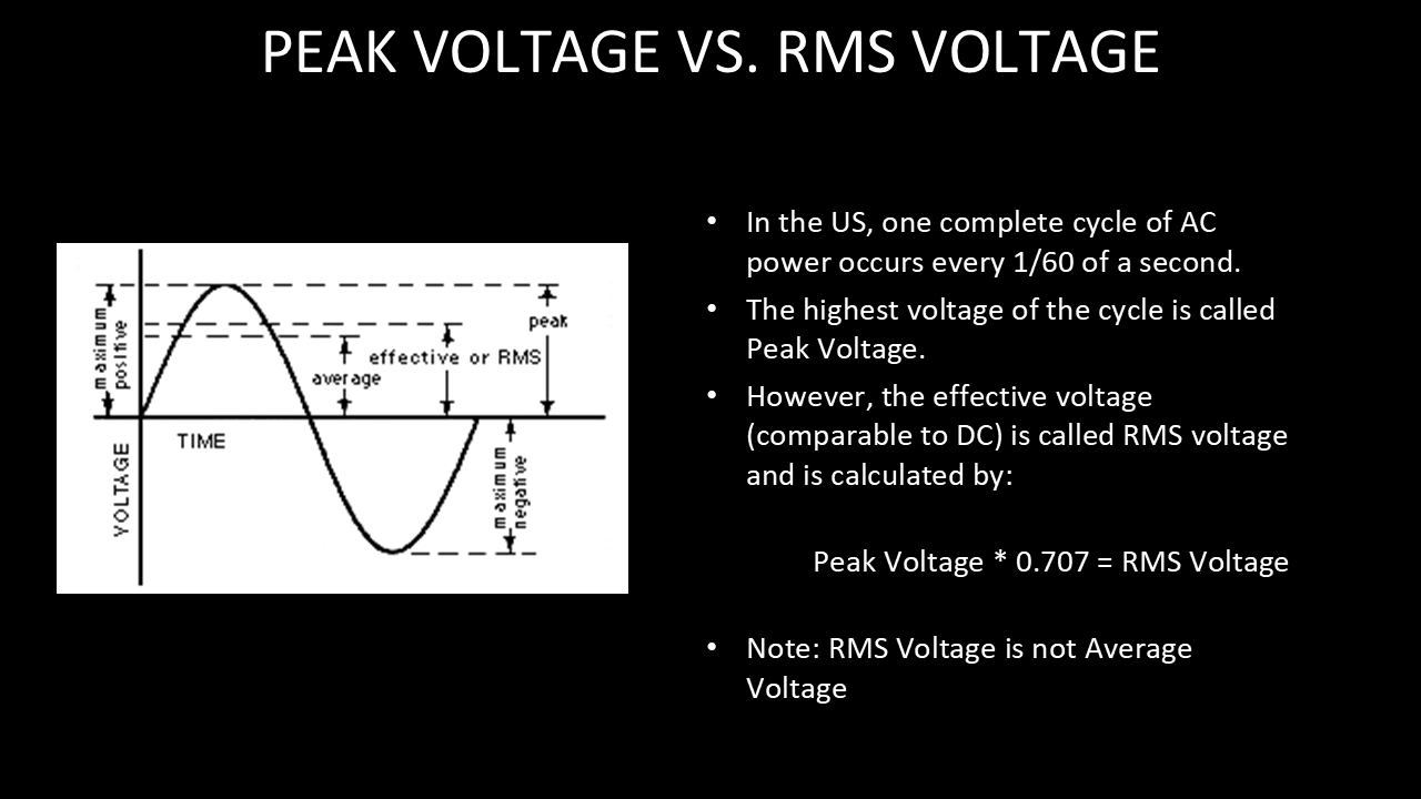
- RMS
- Peak
- Trace
- Probe
- Oscilloscope
- Signal generator
- Capacitor
- Diode
- Bridge Rectifier
- Boolean
- Toggle
Projects (below):
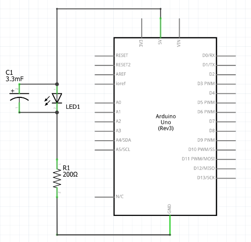
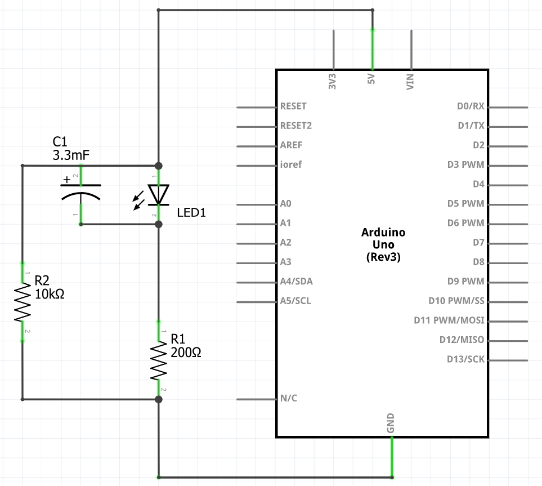
LED w/ capacitor – schematic diagram & wiring
Schematic:
Build:
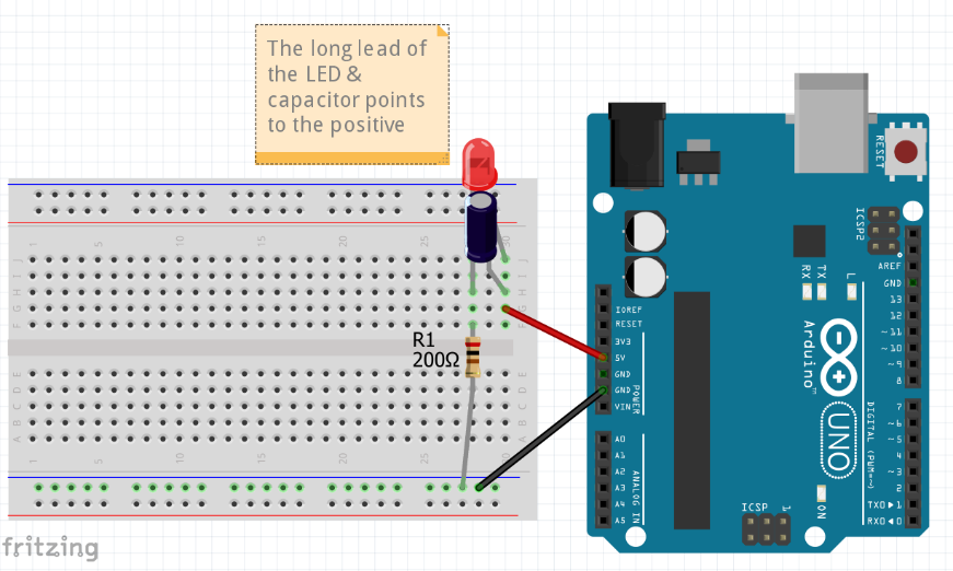
Look at the LED from above, and then disconnect the 5V wire from the Arduino. Observe how the LED stays lit for some time.
LED w/ capacitor & bleeder resistor – schematic diagram & wiring
Schematic:
Build:
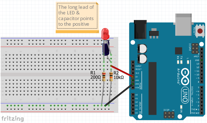
Again, look at the LED from above, and then disconnect the 5V wire from the Arduino. Observe how the LED stays lit for less time than the first time without the bleeder resistor.
Pushbutton toggle – schematic diagram, wiring and code
Schematic:

Build:

Code:
// This code demonstrates toggle button w/ pull-down resistor & LED
const int button1pin = 6;
const int LED1pin = 11;
bool LED1state = false;

void setup() {
  Serial.begin(9600);
  pinMode(button1pin, INPUT);
  pinMode(LED1pin , OUTPUT);
}

void loop() {
 // read the value of the button
  int button1State = digitalRead(button1pin);

  if (button1State == HIGH) {
    LED1state = !LED1state;  // the ! means "not." This toggles LED1state between true and false
    digitalWrite(LED1pin ,LED1state);
    Serial.println("Button is being pressed");
    delay(100); // slight delay to give time for a release
    button1State = digitalRead(button1pin);  // next 4 lines are so holding button won't cause blinking
    while (button1State  == HIGH) {
      delay(100);
      button1State = digitalRead(button1pin);
      }
  }

  delay(100);
}
2 Pushbutton toggle – schematic diagram, wiring and code
Schematic:
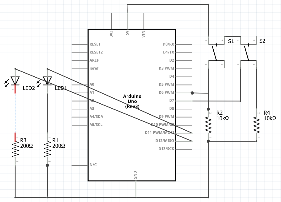
Build:

Code:
// This code demonstrates toggle button w/ pull-down resistor & LED
const int button1pin = 6;
const int button2pin = 7;
const int LED1pin = 11;
const int LED2pin = 12;
bool LED1state = false;
bool LED2state = false;

void setup() {
  Serial.begin(9600);
  pinMode(button1pin, INPUT);
  pinMode(button2pin, INPUT);
  pinMode(LED2pin, OUTPUT);
  pinMode(LED2pin, OUTPUT);
}

void loop() {
 // read the value of the button
  bool button1State = digitalRead(button1pin);
  bool button2State = digitalRead(button2pin);

  if (button1State == HIGH) {
    LED1state = !LED1state;  // the ! means "not." This toggles LED1state between true and false
    digitalWrite(LED1pin ,LED1state);
    Serial.println("Button 1 is being pressed");
    delay(100); // slight delay to give time for a release
    button1State = digitalRead(button1pin);  // next 4 lines are so holding button won't cause blinking
    while (button1State == HIGH) {
      delay(100);
      button1State = digitalRead(button1pin);
      }
  }

  if (button2State == HIGH) {
    LED2state = !LED2state;  // the ! means "not." This toggles LED2state between true and false
    digitalWrite(LED2pin,LED2state);
    Serial.println("Button 2 is being pressed");
    delay(100); // slight delay to give time for a release
    button2State = digitalRead(button2pin);  // next 4 lines are so holding button won't cause blinking
    while (button2State == HIGH) {
      delay(100);
      button2State = digitalRead(button2pin);
      }
  }

  delay(100);
}
Homework:
-
- Rebuild pushbutton project to have two LEDs, each toggled with a different button
- Resistor & Capacitor worksheets
- Bring 9V battery next time
- Watch Diodes Explained: https://www.youtube.com/watch?v=Fwj_d3uO5g8&t
- Watch Capacitors Explained: https://www.youtube.com/watch?v=X4EUwTwZ110&t
- Watch Oscilloscope Tutorial (Basics 101): https://www.youtube.com/watch?v=lSHAE_Y6snc
- Watch Understanding Linear Power Supplies: https://www.youtube.com/watch?v=Wlh20roJiZU
![]()