This is a support page for day 5 of an 8-session class is a basic introduction to both electronics and programming the Arduino microprocessor. The intent is to prepare the student for what is currently popular in the maker world, rather than an electronics or engineering degree, and includes some things of interest to amateur radio enthusiasts.
Day 1, Day 2, Day 3, Day 4, Day 5, Day 6, Day 7, Day 8
Day 5: Making Tones, Transistors, potentiometers, phototransistor, rotary encoder
Goals:
-
- Create your own procedure in C++
- Make electronic tones at given pitches
- Draw the circuit symbol for a transistor
- Explain what a transistor does
- Explain what a potentiometer does
- Explain what a phototransistor does
- Explain how a rotary encoder works
Vocabulary:
-
- Piezo buzzer
- Procedure
- Transistor
- PNP transistor
- NPN transistor
- Phototransistor
- IR LED
- Rotary encoder
Projects (below):
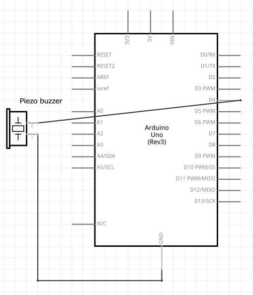
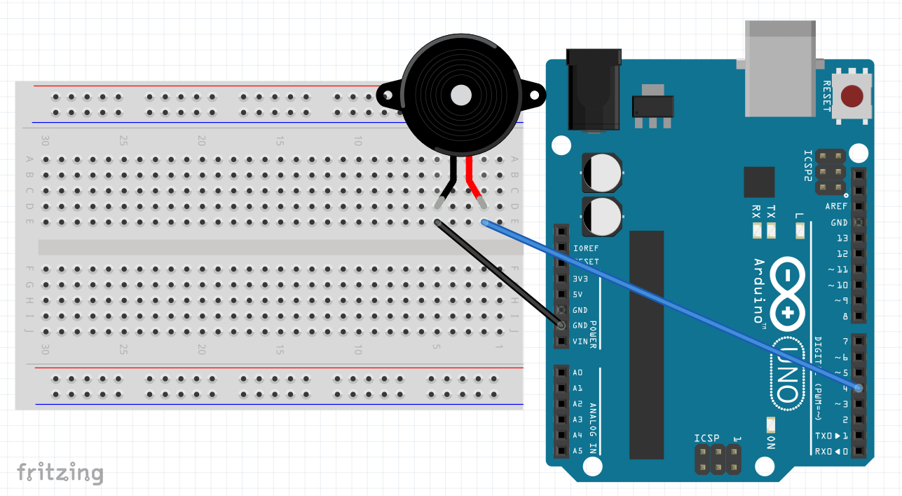
Piezo buzzer – schematic diagram, wiring and code
Schematic:
Build:
Code:
void setup() {
  tone(4, 659, 200);  // tone(pin, freq in Hz, duration in ms)
}

void loop() {
}
const int pin = 4;
const int wait = 20;
const int freqStep = 50;

void setup() {
  for (int i=500; i < 5000; i = i + freqStep) {
    tone(pin, i, wait);  // tone(pin, freq in Hz, duration in ms);
    delay(wait-2);
    }
  delay(100);
  for (int i=5000; i > 500; i = i - freqStep) {
    tone(pin, i, wait);  // tone(pin, freq in Hz, duration in ms);
    delay(wait-2);
    }
    // comment out both delay lines and it "chirps"
  }
}

void loop() {
}
void setup() {
  tone(4, 659, 200);
  delay(300);
  tone(4, 587, 200);
  delay(300);
  tone(4, 523, 200);
  delay(300);
  tone(4, 587, 200);
  delay(300);
  tone(4, 659, 200);
  delay(300);
  tone(4, 659, 200);
  delay(300);
  tone(4, 659, 400);
  delay(500);
  tone(4, 587, 200);
  delay(300);
  tone(4, 587, 200);
  delay(300);
  tone(4, 659, 400);
  delay(500);
  tone(4, 740, 200);
  delay(300);
  tone(4, 740, 200);
  delay(300);
  tone(4, 659, 400);
  delay(300);
  tone(4, 587, 400);
  delay(300);
  tone(4, 523, 400);
  delay(300);
  tone(4, 587, 400);
  delay(300);
  tone(4, 659, 400);
  delay(300);
  tone(4, 659, 400);
  delay(500);
  tone(4, 659, 400);
  delay(500);
  tone(4, 587, 400);
  delay(500);
  tone(4, 587, 400);
  delay(500);
}

void loop() {
}
Transistor circuit w/ 9v battery – schematic diagram, wiring and code
Schematic:
![]()
Build:
![]()
Code:
void setup() {
  pinMode(12, OUTPUT);
}

void loop() {
  digitalWrite(12, HIGH);  // turn the LED on (HIGH is the voltage level)
  delay(1000);             // wait for a second
  digitalWrite(12, LOW);   // turn the LED off by making the voltage LOW
  delay(1000);             // wait for a second
}
Transistor with phototransistor – Schematic, wiring
Schematic:
![]()
Build:
![]()
No Code needed: put a infrared remote’s LED near the phototransistor and your LED should blink.
Transistor with phototransistor + switch & LED – Schematic, wiring
Schematic:
![]()
Build:
![]()
No Code needed: You may need to bend the infrared LED and the phototransistor toward each other. Pressing the switch should make your regular LED turn on. While on, put credit card between the IR LED and the phototransistor. Then place it perpendicularly above both and move it closer, then away.
Homework:
-
-
- Bring a small screwdriver next time
- Watch Transistors Explained: https://www.youtube.com/watch?v=J4oO7PT_nzQ
- Watch NPN / PNP Transistors Explained: https://www.youtube.com/watch?v=zpyK5Hy8d0c
- Add startup alert to project by making a new procedure (void alert {})
- Optional: Build and run Mary (above) or create another tune
-
![]()