This is a support page for day 6 of an 8-session class is a basic introduction to both electronics and programming the Arduino microprocessor. The intent is to prepare the student for what is currently popular in the maker world, rather than an electronics or engineering degree, and includes some things of interest to amateur radio enthusiasts.
Day 1, Day 2, Day 3, Day 4, Day 5, Day 6, Day 7, Day 8
Day 6: Electromagnetism, Relays, Inductors, & RF filters
Goals:
-
- Understand what an electromagnet does
- Explain what a relay does
- Understand what an inductor does
- Use variables in a loop to turn on LED’s
Vocabulary:
-
- Electromagnet
- Relay
- Back EMF
- Inductor
Projects (below):
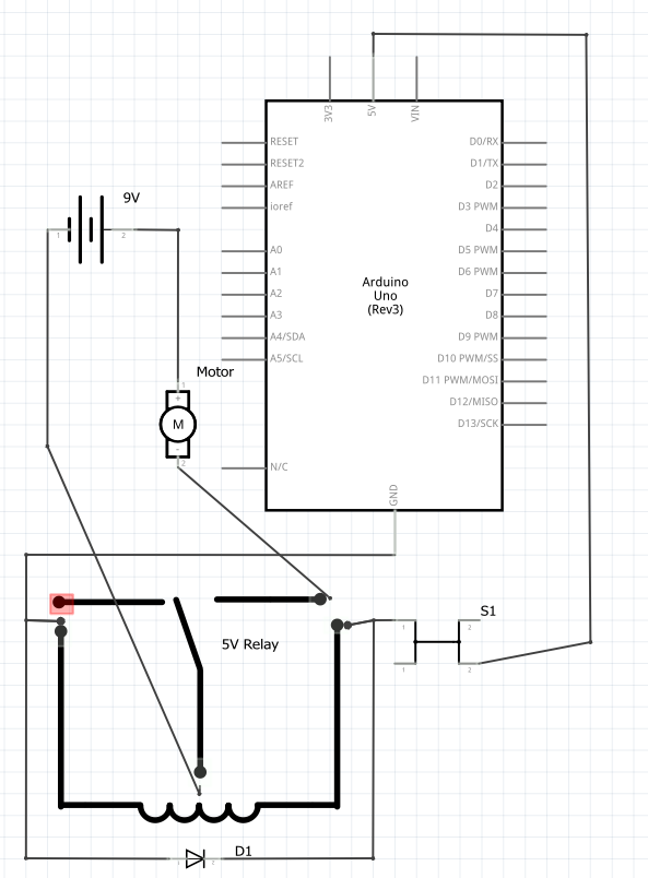
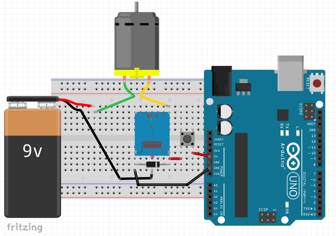
Relay – schematic diagram, wiring
Schematic:
Build:
No code needed.
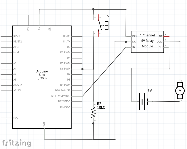
Relay w/ toggle button – schematic diagram, wiring
Schematic:
Build:

Code:
Pushbutton.ino (from Day 4, w/ variable names slightly altered)
Copied!
// This code demonstrates toggle button w/ pull-down resistor & relay
const int btn1pin = 6;
const int relay1pin = 11;
bool relay1state = false;

void setup() {
  Serial.begin(9600);
  pinMode(btn1pin, INPUT);
  pinMode(relay1pin , OUTPUT);
}

void loop() {
 // read the value of the button
  int btn1State = digitalRead(btn1pin);

  if (btn1State == HIGH) {
    relay1state = !relay1state;  // the ! means "not." This toggles relay1state between true and false
    digitalWrite(relay1pin ,relay1state);
    Serial.println("Button is being pressed");
    delay(100); // slight delay to give time for a release
    btn1State = digitalRead(btn1pin);  // next 4 lines are so holding button won't cause blinking
    while (btn1State  == HIGH) {
      delay(100);
      btn1State = digitalRead(btn1pin);
      }
  }

  delay(100);
}
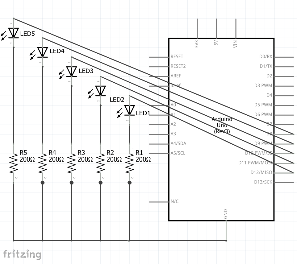
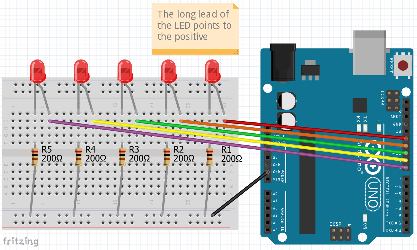
Blink many LEDs with for-loops – schematic diagram, wiring
Schematic:
Build:
Code:
Blink-many-with-loops.ino
Copied!
// This code demonstrates using variables to control LED's
const int wait = 500;

void setup() {
  for (int i = 8; i < 13; i = i + 1) {  // 8 is first LED pin. LED's continue to pin 12
  pinMode(i, OUTPUT);
  }
}

void loop() {
  for (int i = 8; i < 13; i++) {  // i++ is same as i = i + 1
  digitalWrite(i, HIGH);  // turn LED on
  delay(wait);
  digitalWrite(i, LOW);   // turn LED off
  delay(wait);            // experiment with removing or commenting out this line
  }

  for (int i = 12; i > 7; i--) {  // i-- is same as i = i - 1
  digitalWrite(i, HIGH);  // turn LED on
  delay(wait);
  digitalWrite(i, LOW);   // turn LED off
  delay(wait);            // experiment with removing or commenting out this line
  }
}
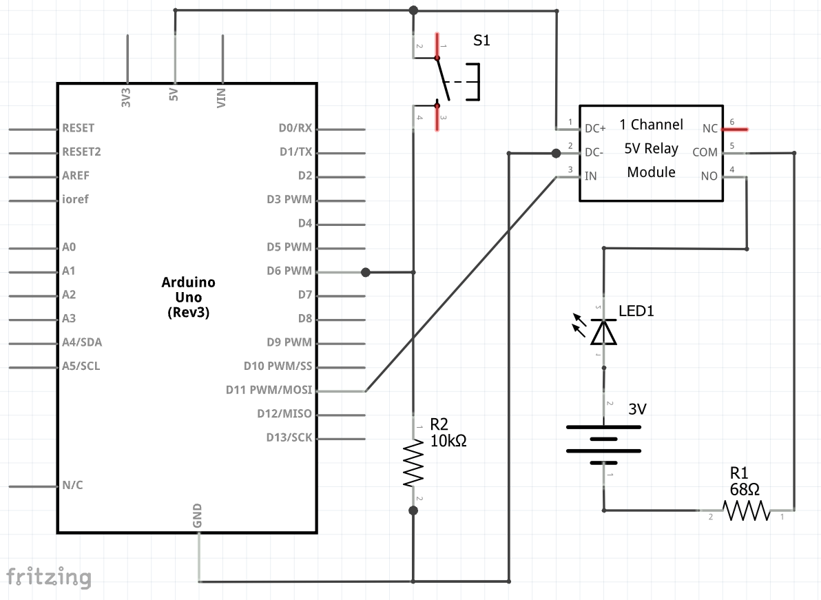
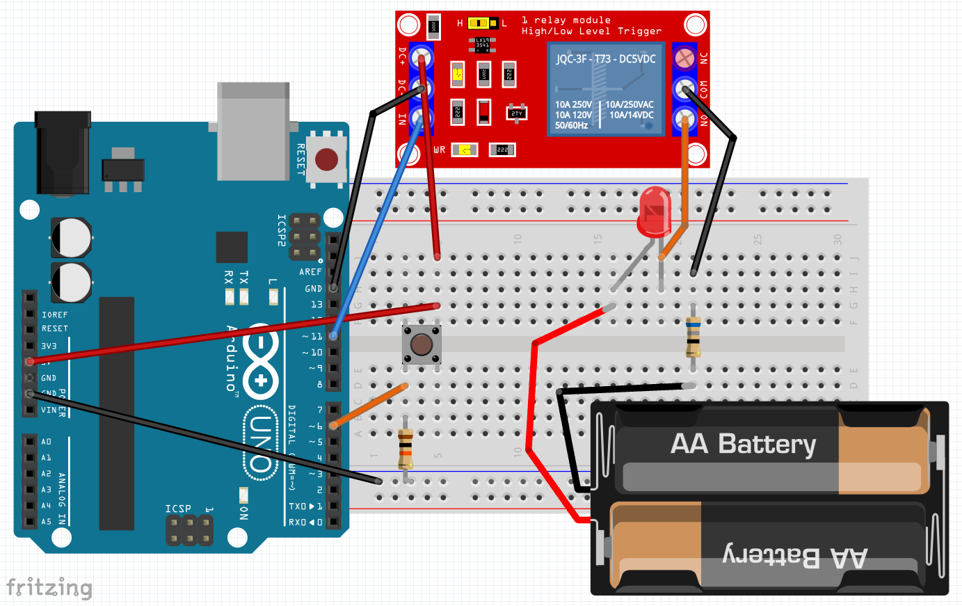
Homework: Relay toggle LED on separate circuit – schematic diagram, wiring
Schematic:
Build:
Code:
Pushbutton.ino (from Day 4, unaltered)
Copied!
// This code demonstrates toggle button w/ pull-down resistor & LED
const int btn1pin = 6;
const int LED1pin = 11;
bool LED1state = false;

void setup() {
  Serial.begin(9600);
  pinMode(btn1pin, INPUT);
  pinMode(LED1pin , OUTPUT);
}

void loop() {
 // read the value of the button
  int btn1State = digitalRead(btn1pin);

  if (btn1State == HIGH) {
    LED1state = !LED1state;  // the ! means "not." This toggles LED1state between true and false
    digitalWrite(LED1pin ,LED1state);
    Serial.println("Button is being pressed");
    delay(100); // slight delay to give time for a release
    btn1State = digitalRead(btn1pin);  // next 4 lines are so holding button won't cause blinking
    while (btn1State  == HIGH) {
      delay(100);
      btn1State = digitalRead(btn1pin);
      }
  }

  delay(100);
}
Homework:
-
- Watch Inductors Explained: https://www.youtube.com/watch?v=KSylo01n5FY
- Rebuild from scratch relay circuit driven by button toggled but use an LED (see above)
![]()